Savolture Technical Guide
48V Battery Cable Size Chart: The ÷4 Rule Explained
Quick answer: For a 48V (51.2V) LFP battery feeding a hybrid inverter on a short run (under ~5–7 ft / 1.5–2 m), size the main battery cable to the inverter's continu...
Quick answer: For a 48V (51.2V) LFP battery feeding a hybrid inverter on a short run (under ~5–7 ft / 1.5–2 m), size the main battery cable to the inverter’s continuous DC current plus a 25% margin, kept under ~3% voltage drop: roughly 6 AWG (16 mm²) for 3 kW, 4 AWG (25 mm²) for 5 kW, 2 AWG (35 mm²) for 6 kW, 1/0 (50 mm²) for 8 kW, 2/0 (70 mm²) for 10 kW, 3/0 (95 mm²) for 12 kW, and 4/0 (120 mm²) for 15 kW. Longer runs need the next size up. Always confirm against your inverter manual, NEC 310.16 ampacity, and a licensed electrician.
Almost every “battery cable size chart” online is built for 12V automotive and RV systems. If you copy one onto a 48V solar storage build, you will over-spec the cable by two gauge sizes — pay for copper you don’t need, and fight to crimp lugs that won’t fit your inverter’s terminals. The physics that everyone misses: at 48V you move the same power at one quarter of the current, so the cable can be dramatically smaller. This chart is built natively for 48V LFP battery-to-inverter wiring, sized the way it’s actually done in the field.
The 48V Battery Cable Size Chart (Battery → Inverter)
This is the main DC cable from the battery bank (or its busbar) to the hybrid inverter. Sizes assume 105°C-rated copper battery/welding cable, a short run, the inverter running at continuous rated power, and a target of 3% or less voltage drop. The current column is the inverter’s continuous DC draw at 48V with a 25% continuous-duty margin applied.
| Inverter (continuous) | Continuous DC current @ 48V | +25% margin | Cable size (AWG) | Metric (mm²) |
|---|---|---|---|---|
| 3 kW | ~63 A | ~78 A | 6 AWG | 16 mm² |
| 5 kW | ~104 A | ~130 A | 4 AWG | 25 mm² |
| 6 kW | ~125 A | ~156 A | 2 AWG | 35 mm² |
| 8 kW | ~167 A | ~208 A | 1/0 AWG | 50 mm² |
| 10 kW | ~208 A | ~260 A | 2/0 AWG | 70 mm² |
| 12 kW | ~250 A | ~313 A | 3/0 AWG | 95 mm² |
| 15 kW | ~313 A | ~391 A | 4/0 AWG | 120 mm² |
Above ~12 kW, many installers run two smaller cables in parallel per polarity (for example 2× 1/0) instead of a single 4/0, because thinner cable is easier to route and terminate. For how inverter continuous output ties back to the battery’s own discharge limit, see our hybrid inverter and battery pairing guide — the cable can only ever be as useful as the BMS continuous discharge rating behind it.
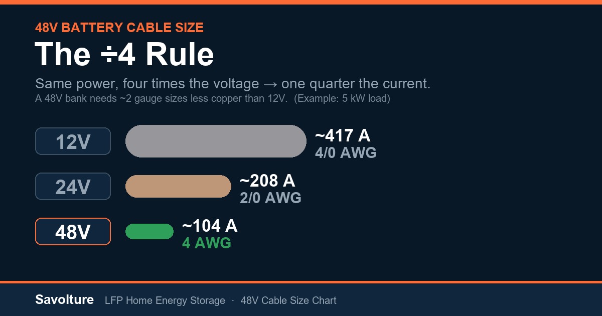
The ÷4 Rule: Why 48V Needs Far Less Cable Than 12V
Power equals volts times amps. Hold the power constant and raise the voltage, and the current — the thing that actually sizes a cable — falls in proportion. A 48V system runs at four times the voltage of a 12V system, so it draws one quarter of the current for the same wattage. That is the single biggest reason 48V has become the default architecture for home storage.
| Same 5 kW load | System voltage | Continuous current | Typical cable |
|---|---|---|---|
| 12V system | 12 V | ~417 A | 4/0 AWG (120 mm²) |
| 24V system | 24 V | ~208 A | 2/0 AWG (70 mm²) |
| 48V system | 48 V | ~104 A | 4 AWG (25 mm²) |
The same 5 kW that needs massive, expensive 4/0 cable at 12V drops to ordinary 4 AWG at 48V — two gauge sizes smaller and a fraction of the copper cost. This is also why a 48V build is cheaper and cleaner to wire overall. If you’re still choosing a system voltage, our 48V vs 24V vs 12V comparison walks through the full trade-off.
Three Cables, Three Different Sizes
“Battery cable” is not one cable. A real 48V install has three distinct runs, and lumping them together is where DIY builds go wrong:
- Battery interconnects — the short jumpers linking battery modules in series or parallel. Each carries the full bank current, so they match (or exceed) the main cable gauge. Use the lugs and torque spec from the battery manufacturer; a loose interconnect is a fire risk.
- Battery bank → busbar / shunt — carries the total system current. Size it to the same chart value as the main run. If you parallel several battery cabinets, each cabinet’s cable carries only its share, but the combined feed to the busbar carries the total.
- Busbar → inverter — the main run in the chart above. This is the one sized to the inverter’s full continuous current.
Sizing each leg correctly is part of treating the inverter and battery as one system rather than two boxes. The inverter-battery compatibility matrix covers the communication side of that same principle.
How Cable Size Is Actually Determined
Two limits decide the gauge, and you size for whichever is stricter:
- Ampacity — the cable must safely carry the continuous current without overheating. NEC 310.16 and the cable manufacturer’s rating give the ceiling. Apply a 1.25× margin for continuous-duty loads (the inverter can pull rated power for hours).
- Voltage drop — over distance, thin cable wastes energy as heat and starves the inverter at high load. Target 3% or less (2% for performance-critical builds). Voltage drop scales with run length, so a gauge that’s fine at 5 ft may need upsizing at 15 ft.
The voltage-drop formula for a DC run is Vd = (2 × L × I × R) ÷ 1000, where L is one-way length in feet, I is current, and R is the cable’s resistance per 1000 ft. The “2×” accounts for the positive and negative conductors. In practice: keep battery cables as short and direct as the layout allows, and when a run gets long, go up a size rather than chasing the exact percentage. Voltage at rest is a separate question — for that, see our 48V LiFePO4 voltage chart.
Don’t Forget the Fuse and the Lugs
A correctly sized cable still needs overcurrent protection and proper terminations:
- Class-T fuse between the battery positive and the inverter, rated above the inverter’s continuous current but at or below the cable’s ampacity. LFP banks can deliver enormous fault current, and a Class-T fuse has the interrupt rating to handle it where automotive (ANL) fuses may not.
- Lugs and crimps matched to the cable gauge and the terminal stud size. A hydraulic-crimped, tinned-copper lug torqued to spec is the difference between a clean connection and a hot, high-resistance joint that loosens over time.
- Match the inverter terminal — check the maximum lug size the inverter’s battery terminals accept before you buy cable. This is exactly why over-sizing from a 12V chart backfires: 4/0 lugs won’t fit a terminal designed for 2 AWG.
Common 48V Cable Sizing Mistakes
- Using a 12V chart on a 48V system. The most common mistake we see. Installers we supply who come from the 12V world routinely over-spec by two gauges — wasting money and ending up with lugs that won’t fit the inverter. Use a 48V-native chart.
- Sizing to nominal power, ignoring continuous duty. A 12 kW inverter can pull 12 kW for hours. Size to continuous current with the 1.25× margin, not to a brief peak figure.
- Ignoring run length. A cable that passes on ampacity can still fail on voltage drop over a long run. Check both; upsize for distance.
- Mismatched lugs or under-crimped terminals. A poor crimp creates a high-resistance hot spot. Use the right lug and a proper crimper, not a hammer.
- No Class-T fuse, or an under-rated one. LFP fault current is high; the fuse must have the interrupt rating to match.
- Mixing cable gauges across parallel battery runs. Unequal cable lengths or gauges make one battery do more work, age faster, and trip first. Keep parallel runs identical.
Sources & Further Reading
- NEC (NFPA 70) Article 310.16 — conductor ampacity tables for current-carrying capacity.
- NEC Article 706 — energy storage system installation requirements.
- ABYC E-11 — AC and DC electrical systems standard (the marine reference widely used for DC battery wiring best practice).
- Blue Sea Systems — DC circuit wizard and ampacity/voltage-drop methodology for battery cabling.
Frequently Asked Questions
What size cable do I need for a 48V 5000W inverter?
For a 5 kW (5000W) inverter on a 48V battery with a short run under ~5–7 ft, 4 AWG (25 mm²) copper battery cable is the typical choice — it covers the roughly 104 A continuous draw plus a 25% margin at under 3% voltage drop. For longer runs, step up to 2 AWG. Always confirm the maximum lug size your inverter terminals accept.
Can I use a 12V battery cable chart for a 48V system?
No — and doing so over-sizes the cable badly. A 48V system carries one quarter of the current of a 12V system for the same power, so it needs roughly two gauge sizes smaller. Using a 12V chart wastes money on copper and often leaves you with lugs too big for the inverter’s terminals. Use a 48V-native chart.
How do I account for cable length and voltage drop?
Size first for ampacity (the cable must carry the continuous current safely), then check voltage drop over your actual run length, targeting 3% or less. Voltage drop rises with distance, so a gauge that’s adequate at 5 ft may need upsizing at 15 ft. When in doubt, go one size larger rather than running thin cable a long way.
What fuse goes between a 48V battery and the inverter?
A Class-T fuse on the battery positive, rated above the inverter’s continuous current but at or below the cable’s ampacity. LFP batteries can deliver very high fault current, and a Class-T fuse has the high interrupt rating needed to clear it safely — something automotive-style fuses may not provide.
Is this chart a substitute for an electrician or local code?
No. This is a planning reference to help you scope a 48V build. Final cable sizing must follow your inverter manual, NEC (and any local amendments) or ABYC for marine, and the judgment of a licensed electrician. Codes and inverter requirements take precedence over any general chart.
Get the Right Cable the First Time
Cable size flows directly from the inverter you choose and the battery behind it. If you tell us your inverter model, target loads, and the run length, we’ll help you spec the battery, confirm the continuous current, and return the matching cable gauge and a bill of materials. Browse the 48V LFP battery platform and the hybrid inverter series, or compare the 100Ah, 200Ah, and 314Ah modules. New to sizing the whole system? Start with our off-grid battery sizing guide.
Ready to size your system?
Get a free battery recommendation.
Tell us your load, location, and backup target — we will spec the right 48V LiFePO4 system for you.