

Savolture Technical Guide
CAN 2.0 vs RS485 BMS Communication Protocol: Complete Technical Guide for Solar & Battery Installers (2026)
Quick Answer: CAN 2.0 and RS485 are the two predominant physical and data link communication layers utilized by LiFePO4 Battery Management Systems (BMS) to interface with hybrid...
Quick Answer: CAN 2.0 and RS485 are the two predominant physical and data link communication layers utilized by LiFePO4 Battery Management Systems (BMS) to interface with hybrid inverters and Energy Management Systems (EMS). CAN 2.0 (governed by ISO 11898-1/2) is a message-oriented broadcast protocol featuring non-destructive bitwise arbitration (CSMA/CA), hardware-level 15-bit CRC, and automated frame acknowledgement (ACK) — operating at standard 500 kbps for BMS integration across Deye, Sol-Ark, Victron, Luxpower, and EG4. RS485 (governed by ANSI/TIA/EIA-485-A and compliant with IEEE 1547-2018 interconnection standards) provides a half-duplex balanced differential physical layer requiring higher-layer framing such as Modbus RTU — operating at 9600 to 115200 bps across Growatt, Voltronic, and select industrial platforms. Commercial BESS platforms (such as the 125 kW / 241-261 kWh utility-grade systems distributed by Savolture, certified to IEC 62619, UL 9540, and UN 38.3) provide dual-port industrial interfaces: CAN 2.0B at 500 kbps (RJ45 Pins 4-5) and RS485 Modbus RTU at 9600 bps (RJ45 Pins 1-2). Field selection hinges on four architectural pillars: Two Physical Layer Baselines (differential signaling and line termination), Three Protocol Stack Layers (framing, baud rates, and collision handling), Five Inverter Integration Scenarios (open vs. closed vendor ecosystems), and Four Critical Troubleshooting Traps (120-ohm termination, pinout transposition, baud mismatch, and closed-firmware handshakes).
Two Physical Layers: ISO 11898-2 (CAN) vs ANSI/TIA/EIA-485-A (RS485) Side-by-Side
Key Takeaway: The physical divergence between CAN 2.0 and RS485 centers on two operational parameters: (1) Signaling and Bus Arbitration — CAN utilizes dominant (logic 0) and recessive (logic 1) differential voltage states enabling non-destructive arbitration at the hardware transceiver level, whereas RS485 uses raw half-duplex differential lines (A/B) with zero native collision arbitration; (2) Bus Topology and Termination — both require a linear daisy-chain topology terminated with 120-ohm resistors at both extreme ends, but CAN strictly caps branch stub lengths to ≤ 0.3 m (30 cm) to avoid transmission line reflections, whereas RS485 tolerates minor wiring variances at lower baud rates. Crucially, multi-pack parallel battery strings natively arbitrate via CAN, whereas RS485 requires higher-layer sequential Modbus master polling to avoid bus contention.
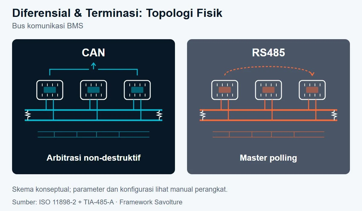
For solar EPC contractors, electrical engineers, and procurement committees evaluating battery and inverter datasheets, the following physical layer parameters govern hardware specification for commercial and industrial (C&I) energy storage systems ranging from 50 kW to 1 MW:
| Physical Layer Parameter | CAN 2.0 (ISO 11898-2) | RS485 (ANSI/TIA/EIA-485-A) | Impact on Battery BMS Integration |
|---|---|---|---|
| Signaling Type | Differential dominant/recessive (CAN-H and CAN-L) | Differential balanced half-duplex (Lines A / B) | CAN delivers superior industrial electromagnetic noise immunity; RS485 ±200 mV receiver sensitivity ensures stability over long cable runs up to 300 m. |
| Collision Arbitration | Non-destructive bitwise arbitration (CSMA/CA; lower ID value wins priority) | None at physical layer (strictly relies on master-slave software scheduling) | Multi-BMS parallel packs on CAN automatically synchronize without collisions; RS485 requires sequential master polling via Modbus RTU. |
| Bus Topology | Linear daisy-chain; maximum stub length ≤ 0.3 m | Linear daisy-chain; short stubs tolerated at low baud | Star topologies are strictly prohibited on both buses for BMS telemetry; reflections corrupt frame reception. |
| Bus Termination | 120 Ω at both extreme physical ends (or dual 60 Ω split termination) | 120 Ω at both extreme physical ends (via DIP switch or terminal resistor) | Missing or improper termination creates standing-wave signal reflections, leading to intermittent packet timeouts. |
| Maximum Physical Nodes | Limited by transceiver differential electrical loading and cable topology per ISO 11898-2 (11-bit identifier space ≠ physical node capacity) | 32 unit loads per segment per ANSI/TIA/EIA-485-A (expandable via repeaters or 1/8th unit load transceivers) | For parallel battery banks > 16 packs, verify transceiver unit load ratings and manufacturer-supported multi-pack topology. |
| Distance vs Baud Rate | 500 kbps → ≤ 100 m; 250 kbps → ≤ 250 m; 125 kbps → ≤ 500 m | 9600 bps → ≤ 1200 m; 115200 bps → ≤ 300 m | Rack-mount battery cables within an ESS cabinet are typically < 3 m, operating comfortably within default margins. |
| Standard Hardware Connector | RJ45 modular jack (Deye, Sol-Ark, Luxpower, EG4) or DB9 (Victron VE.Can) | RJ45 modular jack (Growatt, Voltronic) or industrial screw terminal blocks | Pin assignments are proprietary per manufacturer — there is no universal pinout across different inverter brands. |
Engineering Distinction Note: ISO 11898-2 and ANSI/TIA-485-A define hardware equipment communication layers. They do not constitute personnel safety credentials or cell-level fire safety certifications. Secondary lithium cell safety is certified under IEC 62619 and UL 1973, with full system fire performance certified to UL 9540 and evaluated under UL 9540A testing. On-site commissioning should always be executed by certified professionals (such as licensed Master Electricians or NABCEP-certified solar installers).
Three Protocol Stack Layers: Frame Architecture, Baud Rates, and Error Handling
Key Takeaway: The protocol stack defines how telemetry (cell voltages, State of Charge [SoC], temperature, Charge Current Limits [CCL], and Discharge Current Limits [DCL]) is structured and exchanged above the physical wire: (1) Frame Architecture — CAN 2.0A utilizes an 11-bit identifier with 0 to 8-byte payloads, while CAN 2.0B expands this to a 29-bit extended identifier. Conversely, RS485 relies on Modbus RTU framing consisting of Slave Address (1 byte), Function Code (1 byte), Data payload (up to 252 bytes), and a 16-bit CRC; (2) BMS Baud Rate Baselines — standard CAN 2.0 BMS communication runs at 500 kbps (Deye, Sol-Ark, Luxpower, EG4), with legacy Victron VE.Can operating at 250 kbps. BMS RS485 links run primarily at 9600 bps 8N1 (Growatt, Voltronic), extending to 19200 or 115200 bps in high-speed SCADA networks; (3) Error Detection and Determinism — CAN features automated hardware-level 15-bit CRC, bit stuffing, and instant frame retransmission per ISO 11898-1. RS485 relies entirely on software-level Modbus CRC-16, placing the retransmission burden upon the master controller.
| Protocol Layer Parameter | CAN 2.0 (CAN 2.0A / CAN 2.0B) | RS485 + Modbus RTU |
|---|---|---|
| Frame Architecture | 11-bit standard ID (2.0A) or 29-bit extended ID (2.0B); 0–8 byte payload; SOF + ID + RTR + Control + Data + 15-bit CRC + ACK + EOF | Slave Address (1 byte) + Function Code (1 byte) + Data Payload (0–252 bytes) + CRC-16 (2 bytes); frame boundaries demarcated by > 3.5 character idle time |
| Standard BMS Baud Rates | 500 kbps (Deye, Sol-Ark, Luxpower, EG4, Pylontech, BYD); 250 kbps (legacy Victron VE.Can); 125 kbps (specialized industrial equipment) | 9600 bps 8N1 (Growatt SPH, Voltronic); 19200 bps; 115200 bps (local high-speed industrial SCADA / EMS interfaces) |
| Error Detection & Recovery | 15-bit hardware CRC + bit stuffing + ACK slot + automated hardware retransmission (ISO 11898-1 clause 5) | 16-bit CRC checked in software by receiver; retransmission controlled exclusively by master polling timeout; zero native hardware ACK |
| Network Multi-Master Capability | Native multi-master architecture (any node can broadcast when the bus is idle; collision resolved via ID priority) | Strict single master – multiple slave polling hierarchy; slaves cannot transmit without an explicit request from the master |
| Message Latency & Determinism | Priority-based arbitration delivers bounded latency for highest-priority emergency frames (e.g., 100-bit frame @ 500 kbps ≈ 200 μs transmit duration); lower-priority messages yield based on bus loading | Non-deterministic round-trip latency; total cycle time scales linearly with register polling depth and the number of interconnected slave packs |
| Protocol Transparency & Openness | Open ISO 11898 standard; vendor identifier mapping tables may be publicly documented (Pylontech/Deye) or proprietary (closed OEM platforms) | Open Modbus RTU protocol (Modbus-IDA / Schneider Electric 1979); manufacturer register maps must be provided for EMS/SCADA programming |
Practical Procurement Takeaway: Open protocol architecture dictates whether an energy storage asset can be expanded or serviced over its 10 to 15-year lifecycle. While CAN 2.0 provides superior deterministic responsiveness during grid-failure events, closed proprietary firmware mapping restricts third-party battery compatibility. Conversely, open Modbus RTU registers allow third-party EMS platforms to read raw cell telemetry without vendor licensing constraints. Learn more about system procurement strategies in our C&I BESS Vendor Selection Buyer Guide.
Five Inverter Protocol Selection Scenarios: Field Engineering Taxonomy
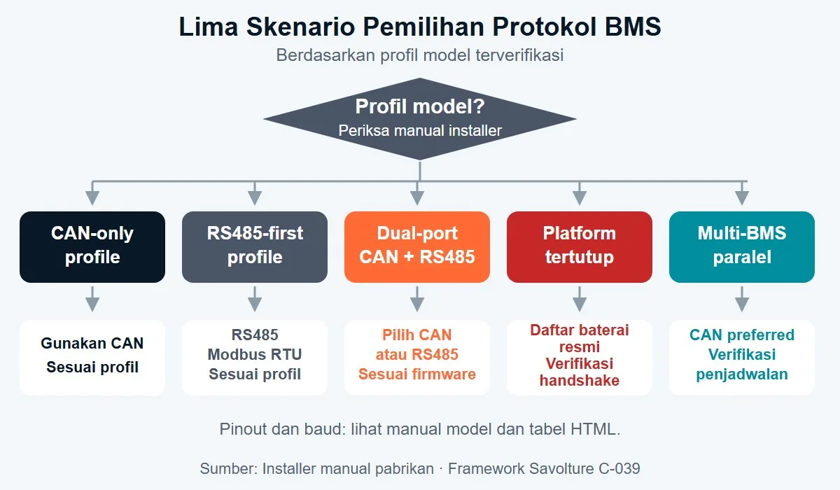
Key Takeaway: Field compatibility requires matching the verified communication profile of the specific inverter model rather than assuming brand-wide uniformity: (1) CAN-Only Inverters (Deye SUN-5K/8K/12K, SUN-125K, Victron MultiPlus-II via Cerbo GX BMS-Can) requiring 500 kbps CAN 2.0; (2) RS485-First Inverters (select Growatt SPH series, Voltronic Axpert King) utilizing 9600 bps Modbus RTU; (3) Dual-Port Hybrid Inverters (Luxpower LXP-5K, EG4 18kPV, Sol-Ark 12K Indoor per Sol-Ark Battery Communications Installation Guide v3.1) offering independent CAN and RS485 ports; (4) Closed Proprietary Platforms (Sungrow SBR/SBH, Huawei LUNA2000, select GoodWe Lynx) requiring proprietary handshake keys; and (5) Multi-Pack Commercial BESS (500 kW to 1 MW systems) where CAN delivers hardware arbitration across parallel battery racks.
Scenario 1 — CAN-Only Inverter Profiles
Inverter models whose technical manuals exclusively expose CAN identifier tables for closed-loop battery communication: Deye low-voltage (SUN-5K/6K/8K/12K SG03LP1) and high-voltage commercial units (Deye SUN-125K-SG02HP3), as well as Victron MultiPlus-II / Quattro systems paired with a Cerbo GX via the dedicated BMS-Can port. Closed-loop CAN integration transmits dynamic CCL/DCL limit values, cell overvoltage/undervoltage cutoffs, and real-time SoC every 100 to 500 ms. Integrating with our 48V LiFePO4 battery lineup or commercial rack systems requires locking the BMS port to CAN 2.0B at 500 kbps, setting Deye LCD battery brand to the appropriate profile (e.g., standard protocol 00 for Deye custom, 01 for Pylontech standard frames).
Scenario 2 — RS485-First Inverter Profiles
Inverters designed primarily around Modbus RTU serial protocols: legacy Voltronic Axpert series and dedicated Growatt SPH energy storage models utilizing the BAT COM port at 9600 bps (8-N-1 format). Crucial Field Note: Newer revisions, such as the Growatt SPH BL-UP series, integrate an auxiliary CAN port alongside RS485. Never categorize protocols purely by inverter brand name — always verify the exact model suffix and installed firmware revision from the manufacturer documentation before cutting RJ45 cable jackets.
Scenario 3 — Explicit Dual-Port Hybrid Inverters
Modern hybrid inverters designed for global battery compatibility provide both physical interfaces: Luxpower LXP-5K Hybrid, EG4 18kPV, and the Sol-Ark 12K Indoor (as documented in the Sol-Ark Battery Communications Installation Guide v3.1, which details dedicated CAN and RS485 physical lines). On dual-port inverters, CAN is the preferred primary channel due to hardware arbitration and bounded message latency; RS485 serves as a reliable secondary fallback. Installers must activate only one protocol at a time in the inverter software settings to eliminate communication bus contention.
Scenario 4 — Closed Proprietary Ecosystems
Platforms such as Sungrow SBR/SBH, Huawei LUNA2000, and select high-voltage GoodWe Lynx stacks utilize physical CAN or RS485 transceivers, but embed encrypted software handshakes and proprietary register mapping. Uncertified third-party battery banks will trigger immediate “Battery Comm Fault” or “Unrecognized Battery Pack” warnings, even if physical wiring, termination resistors, and baud rates are 100% compliant. For procurement teams specifying commercial installations with complete supply chain independence, open-architecture platforms (Deye, Sol-Ark, Luxpower, Victron, Schneider) prevent multi-year vendor lock-in.
Scenario 5 — Multi-Pack Parallel Commercial BESS Architecture
Consider a commercial microgrid facility deploying a multi-pack BESS: for example, 4 units of 125 kW / 261 kWh battery enclosures delivering 500 kW continuous power output and ~1.04 MWh nominal energy storage capacity (with usable energy governed by the operational 80% daily Depth of Discharge [DoD] threshold). In multi-rack parallel configurations, CAN is overwhelmingly preferred over RS485 for three engineering reasons:
- Non-Destructive Bitwise Arbitration: Multiple Master BMS controllers can broadcast over the same bus without data corruption; arbitration occurs instantly at the bit level.
- Deterministic Emergency Signaling: High-priority telemetry frames (e.g., cell over-temperature thresholds, emergency contactor trip alerts) override routine SoC reporting without waiting for a master polling sequence.
- Integrated Battery Combiner Control: Inter-rack balancing and string DC contactor status synchronize automatically across internal rack BMS nodes. For off-grid configurations, explore our dedicated Island Microgrid Battery Diesel Replacement Solution.
Four Critical Communication Traps & Step-by-Step Troubleshooting
Key Takeaway: Over 90% of field commissioning failures between LiFePO4 batteries and solar hybrid inverters trace back to four specific errors: (1) Missing or Incorrect 120 Ω Termination causing signal reflections and intermittent packet loss; (2) Baud Rate Mismatch (e.g., BMS set to 500 kbps while inverter expects 250 kbps) resulting in zero handshake; (3) RJ45 Pin Transposition caused by using generic Ethernet patch cables; and (4) Closed Protocol Lockout. Follow a systematic diagnosis: test line termination with a multimeter → inspect baud rates on LCD displays → verify RJ45 pinout continuity → verify firmware handshake compatibility.
| Communication Trap | Observed Field Symptom | Diagnostic Verification Step | Standard Engineering Resolution |
|---|---|---|---|
| Improper 120 Ω Termination | Intermittent packet drops; “BMS Comm Timeout” cycling every few minutes; frame corruption under inverter load switching. | Power off all DC lines and test resistance between CAN-H and CAN-L (or RS485 A and B) across the bus. Total measured resistance must equal ~60 Ω (two 120 Ω resistors in parallel). | Engage the 120 Ω DIP switch on the terminal battery pack in the daisy-chain; install a 120 Ω metal film resistor across the lines if no internal switch exists. |
| Baud Rate Mismatch | Zero communication handshake; LED activity indicators flash rapidly or stay dark; inverter reports “No Battery Connected”. | Inspect communication baud rate settings in the battery LCD/firmware console and compare with the inverter’s protocol menu (500k vs 250k CAN; 9600 vs 19200 RS485). | Align baud rate parameters to exact identical values on both ends; restart both controllers to establish initial synchronization. |
| RJ45 Pin Transposition | Differential voltage is detectable, but zero valid frames are decoded; continuous hardware CRC checksum errors logged. | Perform continuity pinout tracing with a multimeter: confirm battery transmit pins mate precisely with inverter receive pins per the manufacturer manual. | Crimp a custom RJ45 patch cable matching the exact pin assignments shown in the cross-reference table below; avoid using standard T568A/B patch leads. |
| Closed Protocol Rejection | Physical layer, termination, and baud rate are 100% correct, yet inverter returns “Incompatible Battery Brand” or “Authentication Error”. | Verify whether the inverter brand requires proprietary signed handshake tokens (e.g., Huawei/Sungrow) or supports open standard Pylontech/Deye frame maps. | Update BMS firmware with the verified protocol profile for the target inverter, or select open-architecture hybrid inverters. |
RJ45 BMS Communication Pinout Cross-Reference Table for 8 Major Inverter Brands
Key Takeaway: There is no universal RJ45 pinout standard for solar battery BMS communication. Each inverter manufacturer designates unique pin assignments for CAN-H, CAN-L, RS485-A, and RS485-B within their communication ports. Commercial-grade LiFePO4 batteries engineered for multi-inverter integration (such as Savolture rack-mount and industrial storage modules) incorporate configurable RJ45 ports and provide dedicated manufacturer-labeled patch cables for Deye (Pins 4-5), Sol-Ark, Victron (Pins 7-8), and Growatt (Pins 1-2).
| Inverter Brand & Series | Primary Protocol | Baud Rate & Format | RJ45 Port Pinout Mapping | Technical Reference Source |
|---|---|---|---|---|
| Deye SUN-5K/8K/12K SG03LP1 (Low Voltage) | CAN 2.0B | 500 kbps | Pin 4: CAN-H | Pin 5: CAN-L | Deye ESS Integration Manual (CAN port) |
| Deye SUN-125K SG02HP3 (Commercial HV) | CAN 2.0B | 500 kbps | Pin 4: CAN-H | Pin 5: CAN-L | Deye C&I Hybrid Technical Specification |
| Sol-Ark 12K Indoor | CAN 2.0 / RS485 (Dual-Port) | 500 kbps CAN; 9600 bps RS485 | Dedicated Battery CAN / RS485 ports (verify per profile) | Sol-Ark Battery Communications Installation Guide v3.1 |
| Luxpower LXP-5K / LXP-LB Hybrid | CAN 2.0 (Dual: RS485 optional) | 500 kbps CAN / 9600 bps RS485 | Pin 7: CAN-H | Pin 8: CAN-L (CAN); Pin 1: RS485-A | Pin 2: RS485-B | Luxpower Installation and Operation Manual |
| Growatt SPH 6000TL BL-UP | RS485 Modbus RTU | 9600 bps 8N1 | Pin 1: RS485-A | Pin 2: RS485-B | Growatt SPH BAT COM Specification |
| Voltronic Axpert King 5000 | RS485 Modbus RTU | 9600 bps 8N1 | Pin 3: RS485-A | Pin 4: RS485-B | Voltronic BMS Communication Technical Note |
| Victron MultiPlus-II via Cerbo GX (BMS-Can) | CAN 2.0 (BMS-Can) | 500 kbps (or 250 kbps selectable) | Pin 7: CAN-H | Pin 8: CAN-L | Pin 3: GND | Victron Cerbo GX & VE.Can / BMS-Can Manual |
| EG4 18kPV All-in-One Inverter | CAN 2.0 (Preferred) | 500 kbps | Pin 4: CAN-H | Pin 5: CAN-L (BATT COM1) | EG4 18kPV Installer & Integration Guide |
Installation Reminder: Manufacturer firmware upgrades may alter pin functionality or introduce additional protocol modes. Always verify the active firmware revision on both the inverter and battery BMS prior to on-site commissioning. In multi-rack installations incorporating our 314Ah LFP battery modules, dedicated pre-crimped and tested patch leads should be used in place of hand-crimped field cables.
Commercial BESS Integration: Architecture & Procurement Checklist
Selecting the correct communication architecture is fundamental to ensuring the 10-year operational reliability and bankability of commercial solar-plus-storage systems. Savolture provides engineered B2B energy storage platforms (ranging from 15 kWh server rack batteries to 125 kW / 241–261 kWh containerized C&I BESS) manufactured with Tier-1 LFP cells certified to IEC 62619, UL 9540, and UN 38.3. Every platform integrates open dual-port industrial controllers supporting both CAN 2.0B (500 kbps) and RS485 Modbus RTU (9600–115200 bps).
Before signing procurement contracts for commercial and industrial energy storage assets, ensure your technical review committee validates the following 5 engineering criteria:
- Dual-Interface Redundancy: Does the battery BMS board feature physically separated RJ45 or terminal ports for CAN 2.0 and RS485 Modbus RTU?
- Documented Register & Identifier Maps: Has the supplier provided an unredacted Modbus register map and CAN identifier table for third-party SCADA and Energy Management System (EMS) integration?
- Termination Switch Accessibility: Are internal 120 Ω termination resistors selectable via external DIP switches without opening sealed battery enclosures?
- Multi-Pack String Arbitration: For parallel battery banks exceeding 200 kWh, does the BMS master controller support non-destructive CAN arbitration to manage string balancing and high-voltage DC contactor sequencing?
- Firmware Handshake Transparency: Is the inverter battery brand profile field-configurable to open standards (e.g., standard Pylontech or Deye protocols) to eliminate proprietary vendor lock-in?
Engineering Support & Technical Consultation: Need to verify inverter compatibility, request custom pinout wiring diagrams, or evaluate commercial BESS specifications for an upcoming solar-plus-storage project? Connect with Savolture’s technical integration team through our official B2B engineering portal or explore our comprehensive product lineup at Savolture Hybrid Inverters & Batteries.
Frequently Asked Questions (FAQ)
What is the primary difference between CAN 2.0 and RS485 in solar battery BMS applications?
CAN 2.0 is a complete message-oriented broadcast protocol (covering physical and data link layers per ISO 11898-1/2) that incorporates hardware-level non-destructive bitwise arbitration, 15-bit CRC, and automated frame acknowledgment (ACK). RS485 is purely a balanced differential physical layer (governed by ANSI/TIA/EIA-485-A) with zero native collision handling, requiring an upper-layer application protocol like Modbus RTU for master-slave polling and framing. CAN excels in multi-BMS parallel configurations with deterministic priority scheduling, whereas RS485 requires sequential master polling.
What are the standard baud rates for CAN and RS485 battery BMS communication?
For CAN 2.0 BMS communication, the industry standard is 500 kbps (utilized by Deye, Sol-Ark, Luxpower, EG4, Pylontech, and BYD), with legacy Victron VE.Can operating at 250 kbps. For RS485 BMS communication, the standard default is 9600 bps with 8N1 framing (Growatt SPH, Voltronic), extending to 19200 or 115200 bps in high-speed industrial SCADA and EMS deployments. The baud rate must match identically on both the battery and inverter to establish a valid handshake.
Is a 120-ohm termination resistor mandatory on CAN and RS485 buses?
Yes. A 120-ohm termination resistor is mandatory at each of the two extreme physical ends of both CAN and RS485 linear daisy-chain buses. When measured across CAN-H and CAN-L (or RS485 A and B) on a powered-down bus, the multimeter must read approximately 60 ohms (representing two 120-ohm resistors in parallel). Missing termination causes standing-wave signal reflections and intermittent packet loss, frequently triggering cyclic communication timeouts on the inverter.
Is there a universal RJ45 pinout standard for solar battery BMS communication?
No. There is no universal RJ45 pinout standard across the solar storage industry. Different inverter manufacturers designate unique pin assignments within their communication jacks: Deye uses Pins 4-5 for CAN, Growatt utilizes Pins 1-2 for RS485, Victron VE.Can maps to Pins 7-8, and Luxpower uses Pins 7-8 for CAN and Pins 1-2 for RS485. Never use generic T568A/B Ethernet patch leads without verifying continuity against the manufacturer pinout tables.
Can third-party LiFePO4 batteries communicate with closed platforms like Sungrow or Huawei?
While physically compatible at the electrical transceiver level (standard CAN or RS485), closed proprietary platforms such as Sungrow SBR/SBH and Huawei LUNA2000 require encrypted firmware authentication handshakes. Uncertified third-party batteries will be rejected with an “Unrecognized Battery” fault code. For long-term procurement flexibility, engineering teams should specify open-architecture inverters (such as Deye, Sol-Ark, Luxpower, Victron, and EG4).
Why is CAN preferred over RS485 for multi-pack parallel commercial BESS installations?
CAN is preferred for multi-pack parallel battery systems due to three critical architectural advantages: (1) Non-destructive bitwise arbitration enables multiple battery rack controllers to broadcast simultaneously without packet collisions; (2) Priority-based message scheduling delivers bounded transmission latency for emergency alerts (e.g., cell overvoltage or thermal runaway events) without waiting for sequential polling cycles; and (3) Hardware-level 15-bit CRC and instant automatic retransmission ensure robust telemetry in high-noise industrial power environments.
References & Engineering Standards
- ISO 11898-1:2015 — Road vehicles — Controller area network (CAN) — Part 1: Data link layer and physical signalling. International Organization for Standardization.
- ISO 11898-2:2016 — Road vehicles — Controller area network (CAN) — Part 2: High-speed medium access unit. International Organization for Standardization.
- ANSI/TIA/EIA-485-A — Electrical Characteristics of Generators and Receivers for Use in Balanced Digital Multipoint Systems. Telecommunications Industry Association.
- Modbus Organization — Modbus over Serial Line Specification and Implementation Guide V1.02. Open standard specification.
- IEC 62619:2022 — Secondary cells and batteries containing alkaline or other non-acid electrolytes — Safety requirements for secondary lithium cells and batteries, for use in industrial applications.
- UL 9540:2023 — Standard for Energy Storage Systems and Equipment. Underwriters Laboratories.
- UL 9540A — Test Method for Evaluating Thermal Runaway Fire Propagation in Battery Energy Storage Systems.
- NFPA 855:2023 — Standard for the Installation of Stationary Energy Storage Systems. National Fire Protection Association.
- IEEE 1547:2018 — Standard for Interconnection and Interoperability of Distributed Energy Resources with Associated Electric Power Systems Interfaces.
- Deye ESS Inverter Manual — Low Voltage and High Voltage C&I Battery Communication Specification (2026 Edition).
- Sol-Ark — Battery Communications Installation Guide v3.1 (Technical Integration Manual).
- Victron Energy — Cerbo GX & VE.Can / BMS-Can Communication Documentation.
Ready to size your system?
Get a free battery recommendation.
Tell us your load, location, and backup target — we will spec the right 48V LiFePO4 system for you.